Author Topic: Programming the Vector Controller  (Read 68023 times)

Offline Bikemad

  • Global Moderator
  • Professor
  • PhD. Magic
  • ******
  • Posts: 5,494
Re: Programming the Vector Controller
« Reply #60 on: May 21, 2018, 09:59:43 AM »
If the changes you have made are not noticeable, then either they were not "downloaded to the controller" properly or they need to be changed a bit more until you get it working as best as you can.

At least with Bluetooth, you can easily change the settings on the bike and quickly test the effect of the changes.  ;)

If the PAS is still not working at lower pedal cadence, you may be able to add more magnets to the magnet ring on the pedelec sensor (if you can find suitable magnets).

Alan
 

Offline Stegolden

  • Confirmed
  • New Member
  • *
  • Posts: 12
Re: Programming the Vector Controller
« Reply #61 on: May 22, 2018, 02:21:23 PM »
Hi Alan,
yes with bluetooth is too easy.

now i've changed and put these settings:

pas ratio 100
battery drawn current 10
rated phase 35
max forward speed 200
acceleration 50

with level 1 help me only with high cadence frequence
with level 2-3-4-5 the motor help me but with same power

any suggestions?


Offline Bikemad

  • Global Moderator
  • Professor
  • PhD. Magic
  • ******
  • Posts: 5,494
Re: Programming the Vector Controller
« Reply #62 on: May 23, 2018, 09:42:00 PM »
I don't know what else to suggest, if you can't improve it any more by adjusting the settings, then another way to improve the PAS is to purchase a PAS Torque Sensor to enable the motor to provide power relative to the pedal pressure instead of the cadence.

I'm not sure if these will work on their own, or whether a Cycle Analyst is also required.

Here is the user guide for the Torque sensor, but if you need further information, Gary (GM Canada) may be able to answer questions on that particular setup.

Alan
 

Offline Stegolden

  • Confirmed
  • New Member
  • *
  • Posts: 12
Re: Programming the Vector Controller
« Reply #63 on: June 07, 2018, 10:13:14 AM »
Hi,
now i've solved the problems on cadence.

with different sensor and magnets i've a quickly response from motor.

just the problem on the levels remain.......with level 1 or level 5 I get ever same assistance!


Offline Phoogiman

  • Confirmed
  • New Member
  • *
  • Posts: 2
  • Take it Easy, but TAKE it!
    • Philips hjemmeside
Re: Programming the Vector Controller
« Reply #64 on: November 11, 2020, 01:55:54 PM »
First of all, thank you in advance for reading and helping out.

The case:

I want to change Maximum Forward Speed from 380 to 700 because at the moment the topspeed is set to 30 km/h, it is a 26" wheel so should be able to go +40 km/h.

My Pie 3 on the same bike could go over 40 km/h and I could edit the RPM however I wanted. I am confused as you can tell.

I have done settings before on previous series but this Pie is testing me.

I can change other settings like Reverse Enable or the Voltage - but when I change the RPM it defaults back to 380.


Following every step from Bikemads post on the first page:

"First you’ll need to install the correct driver for the USB lead (download and run CH341SER.EXE USB driver in the above link) and download the programming software (LBMC_GUI_v3.3.0_GoldenMotor.exe in the above link).
 
Here is the important sequence that must be followed in order to connect successfully:
1) Connect the USB lead. (Vector controllers use a USB lead fitted with a five pin connector, see below)
2) Open the software that you downloaded previously.
3) Select the correct COM port from the dropdown option box (if you don’t know which COM port the USB lead is assigned to you will have to repeat the whole process selecting a different port each time until you find the right one).
4) Click the “Connect” icon and wait for the timeout error.
5) Then connect the battery power!!
The controller should instantly connect and the relevant parameters should automatically be uploaded and displayed.

When the alterations have been saved to the controller you need to unplug the USB lead and then switch the battery power off and then back on again for the controller to work."


It connects fine with Windows 10 - I also tried to open the PI-800 software in compatibility mode Windows 7 with full rights, it did not make any difference. Also 5-pin+ports are working as intended. I also updated the USB driver.


I then unplug the USB lead and then switch the battery power off and then back on.. Nothing, back to 380.

If you know what I am doing wrong please let me know, I want it to run 100% unlimited.

Cheers, Phoogieman

Edit:
Magic 5 Pie
Controller G
Ping Battery 48v / 20 Ah
Wheel: 26"
Controller: BAC-0501
« Last Edit: November 11, 2020, 03:00:55 PM by Phoogiman »

Offline Bikemad

  • Global Moderator
  • Professor
  • PhD. Magic
  • ******
  • Posts: 5,494
Re: Programming the Vector Controller
« Reply #65 on: November 11, 2020, 04:58:11 PM »
Hi andto the forum,

I don't think you are doing anything wrong but I suspect the controller has been set to allow a maximum of 380 rpm.
The controller is limited to an absolute maximum battery voltage of <63V (the maximum safe nominal battery voltage is 48-51.8V).
Even at the absolute maximum battery voltage, the motor's unloaded speed is unlikely to exceed 380 rpm, therefore there is not much point in allowing higher rpm figures to be entered. ???

A 26" wheel spinning at 380 rpm equates to ~47 km/h, so it shouldn't be the 380 rpm that is limiting your top speed.

It is more likely to be a low throttle signal voltage (below 3.25V) or insufficient current being provided to achieve the maximum speed under load.

If you are unable to achieve the expected wheel rpm (or speed) under a no load condition (wheel suspended in mid air) then I suspect it is either the throttle itself, or more likely a low +5V supply from the controller.
If the +5V supply to the throttle is too low, then the throttle would be unable to output the 3.25V required to achieve maximum rpm.  ;)

You should be able to check the actual +5V supply voltage by measuring it in relation to battery negative (ground) at the pedelec connector or one of the brake switch connectors:


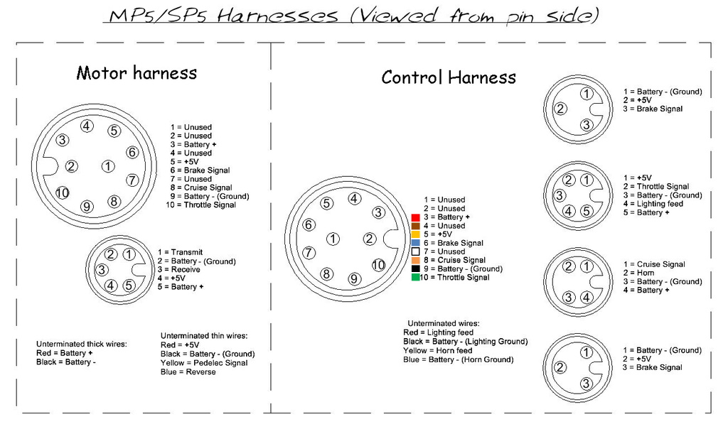
If you place a short piece of wire insulation on the end of the Positive meter probe (or wrap some insulation or masking tape around it to make a tube) it will prevent the probe from accidentally touching against adjacent pins while you are checking the voltage on the +5V supply pin:


The +5V supply should ideally be between 4.5~5 Volts, but your throttle may still produce a full throttle signal output voltage (at least 3.25V) with slightly less than 4.5V on the +5V supply.

P.S.  I have just checked one of my controllers to see what voltage readings you should expect to see:
The +5V supply was reading a constant ~4.9V with the throttle and Bluetooth dongle disconnected.
When I plug just the throttle in, it drops to 4.23V.
When I plug just the Bluetooth dongle in, it drops to 4.52V.
When both units are plugged in, it drops to 4.22V

Please keep us updated with your findings as it may well help others who may be experiencing a similar lack of top speed.

Alan
 

Offline Phoogiman

  • Confirmed
  • New Member
  • *
  • Posts: 2
  • Take it Easy, but TAKE it!
    • Philips hjemmeside
Re: Programming the Vector Controller
« Reply #66 on: November 12, 2020, 04:48:23 PM »
Yes I have tested already
3.7V on the throttle (+5v)line

What can I do?

Offline Bikemad

  • Global Moderator
  • Professor
  • PhD. Magic
  • ******
  • Posts: 5,494
Re: Programming the Vector Controller
« Reply #67 on: November 12, 2020, 10:11:32 PM »
If the 3.7V was measured with the throttle disconnected, it will probably be even lower when the throttle is plugged in:
3.3 volts with dongle plugged in and throttle unplugged.
2.04 volts with dongle and throttle connected

It is probably a weak 5V regulator (which is an integral part of the controller) so if it's still under warranty I suggest that you contact your supplier and explain the problem to them, as a replacement controller may be needed to rectify the low +5V supply.

However, if it's out of warranty, you might want to try adding an external +5V supply to see if it overcomes the problem.

You could start with three AA or AAA cells connected in series connected between battery - and the +5V wire to see if it cures the low top speed problem, and these could hopefully be replaced with a simple 60V to 5V DC/DC converter for a more permanent solution.

It might also be possible to use a 10K Multiturn Potentiometer as a simple voltage divider to boost the low +5V supply.
I don't know if there is sufficient room to fit this item inside the throttle, but would be a convenient place to install it as the throttle housing already contains the Battery +, Battery - and +5V wires inside.  ;)

The potentiometer would need to be initially adjusted to provide an output of ~5V with a fully charged battery before connecting it to the +5V supply wire, but once connected, it should be possible to adjust it slightly if necessary to ensure that the +5V wire is still set to the expected ~5V.

Alan
 

Offline Pramot

  • Confirmed
  • New Member
  • *
  • Posts: 4
Re: Programming the Vector Controller
« Reply #68 on: February 26, 2021, 02:56:33 PM »
If the 3.7V was measured with the throttle disconnected, it will probably be even lower when the throttle is plugged in:
3.3 volts with dongle plugged in and throttle unplugged.
2.04 volts with dongle and throttle connected

It is probably a weak 5V regulator (which is an integral part of the controller) so if it's still under warranty I suggest that you contact your supplier and explain the problem to them, as a replacement controller may be needed to rectify the low +5V supply.

However, if it's out of warranty, you might want to try adding an external +5V supply to see if it overcomes the problem.

You could start with three AA or AAA cells connected in series connected between battery - and the +5V wire to see if it cures the low top speed problem, and these could hopefully be replaced with a simple 60V to 5V DC/DC converter for a more permanent solution.

It might also be possible to use a 10K Multiturn Potentiometer as a simple voltage divider to boost the low +5V supply.
I don't know if there is sufficient room to fit this item inside the throttle, but would be a convenient place to install it as the throttle housing already contains the Battery +, Battery - and +5V wires inside.  ;)

The potentiometer would need to be initially adjusted to provide an output of ~5V with a fully charged battery before connecting it to the +5V supply wire, but once connected, it should be possible to adjust it slightly if necessary to ensure that the +5V wire is still set to the expected ~5V.

Alan
My Smart Pie controller, 5V regulator was damaged a month ago. Because I bought a pair of electric brake levers that was not from Golden Motor.
Connection pins does not match Golden Motor cable (my mistake that I did't check them before, It has the same 3 pins waterproof connector).
When I replaced one of them and pull the brake lever ,then short circuit happened.
I made external +5V supply from 4 AA rechargeable battery and XL4005 adjustable buck converter to drop voltage to +4.65V
If the voltage is over 4.7V, Throttle will not work properly (It works but not comfortable to use).
Fully charged 4 AA battery can run more than 1,000 kilometers.
I cut and alternate the wires of new brake lever to avoid short circuit.
Thanks Alan.