

 Recent Posts
91
Magic Pie & Smart Pie Discussions / Re: Magic Pie 4 no wheel movement on a custom-built E-Trike
« Last post by Bikemad on March 09, 2025, 12:11:34 AM »I only have a mechanical brake that is installed independently to the Magic Pie wheel and I have not
connected/installed the part of the harness that is meant for the brakes.
Could this be a reason why it does not function?
That won't be causing your problem, as the motor should still work fine without the brake sensors connected.
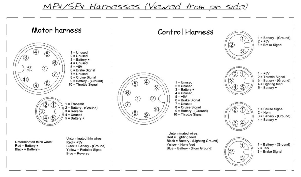
Make sure that the four "unterminated thin wires" coming from the motor harness for Reverse and Pedelec do not have any of their copper cores exposed and touching each other:
It could possibly be a faulty throttle unit that is not sending the correct throttle signal to the controller (Throttle signal voltage should be ~0.8V with throttle released and above 3.25V at full throttle).
If you are considering changing the controller, you might want to remove the controller from the hub and see if the LED on the inside is flashing an error code while the controller is still connected and powered up.
The number of regular flashes relate to different faults:
A single blink from the LED on the controller circuit board is typically seen when the controller is initially powered up (Simple LED test)
1 regular flash indicates Over Voltage Protection
2 regular flashes indicates Under Voltage Protection
4 regular flashes indicates Stall Protection
5 regular flashes indicates Hall sensor input is abnormal
7 regular flashes indicates Phase Wire disconnected
9 regular flashes Communication problem
14 regular flashes indicates Throttle is not in the idle state when system powered on
Alan
 to the forum.


