Author Topic: Magic Pie III wiring problems.  (Read 7417 times)

Offline Sl0wb0b

  • Confirmed
  • New Member
  • *
  • Posts: 7
Magic Pie III wiring problems.
« on: May 27, 2016, 05:26:42 PM »
Hi,
I have troubles to get my Thumbs Gas and the other switches connected to my MP3. The wiring diagrams on the forum here are not clear enough for me to be brave enough to connect/solder my stuff together. Im afraid I damage sth. I got a new battery pack and the Gas Thumb/ other switches didnt came with the round plug which I ordered here in Germany to cut down the delivery time. Please help me get this stuff connected
 The colors of the wires don't match the diagrams. Here is a pic of the cut cables from the switches and the connector on the motor.

Black on the round multi plug from the motor and the thick green one have no resistance so I guess these are ground.
« Last Edit: May 27, 2016, 10:38:01 PM by Sl0wb0b »

Offline Bikemad

  • Global Moderator
  • Professor
  • PhD. Magic
  • ******
  • Posts: 5,508
Re: Magic Pie III wiring problems.
« Reply #1 on: May 28, 2016, 10:16:51 AM »
Hi andto the forum.

Unfortunately there is no set colour association with the functions of the harness as the colours seem to vary between harnesses.

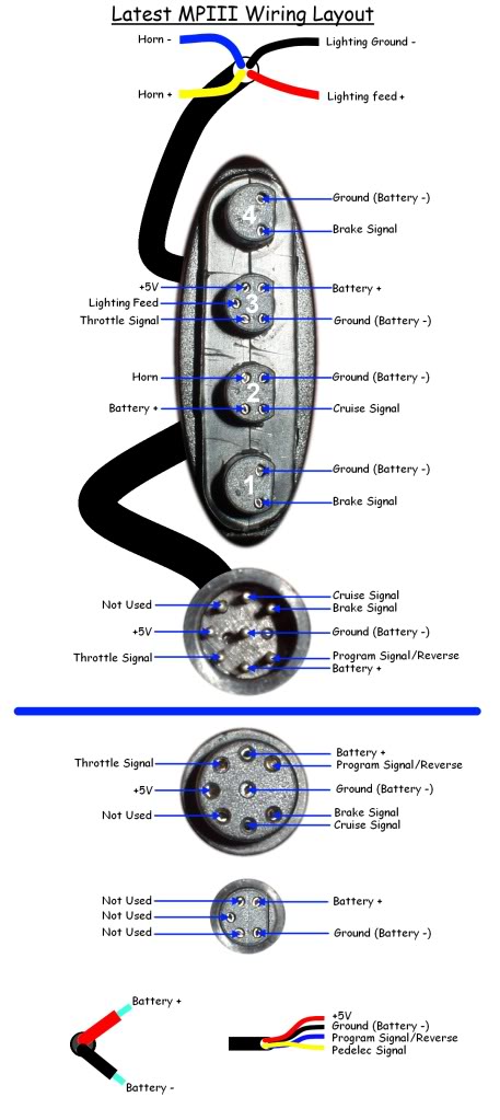
Here is the wiring diagram for the early MPIII which shows the pin allocation but not the wire colours:


As your connector seems to have 9 wires coming from it, I assume yours has the later 10 pin harness as used on the MP4 and MP5 control harness.

The following diagram shows the pin allocation on the 10 pin connector:


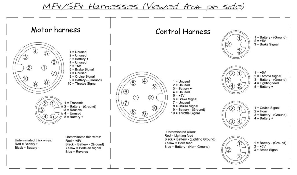
You will need to check for continuity between each pin and each of the coloured wires coming from the connector to determine the function of each of the coloured wires before you can connect them to your replacement controls.

The following diagram shows the wiring connections for the original Magic Pie, which might be useful as it shows the various common ground connections from each of the controls:


Click image to view full size.

The brakes, cruise and horn switches only require two wires each and the polarity of each pair does not matter.
You can use a continuity tester or ohmmeter to determine which pairs of wires are connected when each of the switches is operated if they are not already identified.

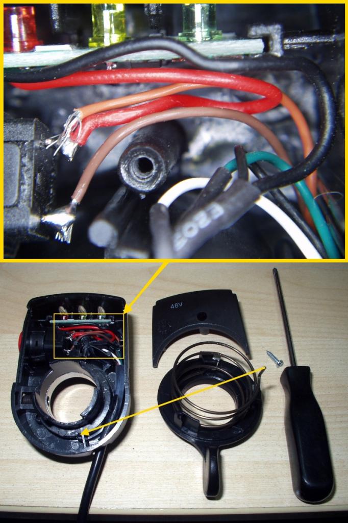
To determine the function of each of the wires coming from the thumb throttle, you may need to open up the throttle unit. I realise your thumb throttle is different to the one shown in the link, but I'm guessing that it will probably come apart in a similar fashion and allow you to take a good look at the wire colours and their associated connections inside.

In the following picture the Hall sensor wires are as follows:
  • White = +5V
  • Black = Ground (0V)
  • Green = Signal output (0.8-4.5V)


Hopefully this information will help with your repair, but if you need further assistance please provide further information with pictures if needed.

Alan
 
« Last Edit: July 04, 2017, 10:54:25 PM by Bikemad »

Offline Sl0wb0b

  • Confirmed
  • New Member
  • *
  • Posts: 7
Re: Magic Pie III wiring problems.
« Reply #2 on: May 28, 2016, 10:49:35 AM »
Thanks a lot, Ill try and give feedback.

Offline Sl0wb0b

  • Confirmed
  • New Member
  • *
  • Posts: 7
Re: Magic Pie III wiring problems.
« Reply #3 on: May 28, 2016, 12:28:15 PM »
Its a 8 pin conector. The colors are confusing me. Here are some pics.

Offline Bikemad

  • Global Moderator
  • Professor
  • PhD. Magic
  • ******
  • Posts: 5,508
Re: Magic Pie III wiring problems.
« Reply #4 on: May 28, 2016, 01:51:33 PM »
I don't know about the colours, it's that pin configuration that is confusing me!

Your photo shows an 8 pin mini DIN female connector which has the centre pin offset, and is the same as the connectors fitted to the motor harness (not the main control harness) on the original Magic Pies and MPII, but I have not seen these connectors used on an MPIII.

If your motor is an MPIII it should have the cooling fan brake disc mount like the motor shown on the right, but I suspect it is an MPII which should look like the motor on the left:


If you actually have an MPII (or earlier) and have cut this connector off the end of your motor harness, you will not be able to program the controller without it. If the controller needs to be programmed you will need to reattach the connector to the motor harness along with the new control connections.

To find out the function of each of those wires, you will need to check the continuity between each pin in the connector and each of the wires until you find the pairs of wires and pins that have continuity and then label the wires according to this diagram to show each wire's function:


(On Magic Pie II controllers, the Yellow wire shown as "Not Used" in the above diagram is actually used for programming the controller and for selecting the reverse function.)

You can then simply transfer the functions of each coloured wire onto the motor harness so you will hopefully know which wires your controls will need to connect to.

Alan
 
« Last Edit: July 04, 2017, 09:49:34 PM by Bikemad »

Offline Sl0wb0b

  • Confirmed
  • New Member
  • *
  • Posts: 7
Re: Magic Pie III wiring problems.
« Reply #5 on: May 29, 2016, 12:31:09 AM »
Thank you again for your posts. Im making progress and I know that the white/red/black one are on the right positions. I gave power to the controller (48+ on the thick red wire and ground on the"green" one, obviously not black). I read 4.95V on the red to the black one and 4.5 V on the green to the black one. The white one to the black one has 0.2V.
« Last Edit: May 29, 2016, 06:08:07 AM by Sl0wb0b »

Offline Sl0wb0b

  • Confirmed
  • New Member
  • *
  • Posts: 7
Re: Magic Pie III wiring problems.
« Reply #6 on: May 29, 2016, 12:42:41 AM »
The wheel is moving thank you guys :)

White from throttle on red from controller. Black on black. Green on white.

Edit: Bike is running great, nice top speed. Im curious if there are any bad side effects if I active brake regen on my Sony VTC5s. If I reduce brake regen percentage in the software the recharge current should be reduced I guess. My recent setting is 45%.
« Last Edit: May 29, 2016, 06:26:40 AM by Sl0wb0b »

Offline Bikemad

  • Global Moderator
  • Professor
  • PhD. Magic
  • ******
  • Posts: 5,508
Re: Magic Pie III wiring problems.
« Reply #7 on: May 29, 2016, 11:18:46 AM »
Good to hear you've got it working.

Assuming your Sony cells are genuine and not fake, they should have a typical charge current of 2.5A per cell, and probably a lot less if they are fake.

So a 10Ah pack should be charged at a maximum of 10A, and a 20Ah pack would be 20A etc.

If your pack is 20Ah or more , then regen current should not be a problem, but if your pack is only 10Ah, you really should have some form of current measuring device (Ammeter, Cycle Analyst or Wattmeter etc.) to check that your regen current isn't exceeding the recommended charging current for your pack.

Alan
 

Offline Sam.Vanratt

  • Confirmed
  • Bachelor of Magic
  • ****
  • Posts: 116
Re: Magic Pie III wiring problems.
« Reply #8 on: May 29, 2016, 05:56:33 PM »
Hi Sl0wb0b
remember that not all cells like to be charged/discharged that (few seconds high Amperage charge, then discharge) way. My first KONION cells Pack failed (only 60% capacity left) after only 7 month (~160 charges). After disabling regen at that bike they kept at that capacity  since the last 500 charges. To use Regen (which I like enormously) I added a Ultracap charging module to my Sinopoly LiFePO4 Packs, so I never charge back to the battery, but only to the Ultracaps, which likes to be charged/discharged in seconds. My newest pack contains WINA cells which explicitly allows such treatment. If you use  Regen a lot you should as well considering a better (no 30 USD BMC) BMS to be able to distribute the current not only in the "above the limit" situation (so called window comparators) but in any case leveled to the cell condition.
So you should watch the capacity of your cells in the first month to stop treating them "bad".
Cheers
Sam

Offline Sl0wb0b

  • Confirmed
  • New Member
  • *
  • Posts: 7
Re: Magic Pie III wiring problems.
« Reply #9 on: June 09, 2016, 06:11:56 AM »
ok ty for the information. how to build these ultra caps? as a shunt? I use 50 per cent of the softwares 100 for recuperation. I get one of these cheap gt power as measurement device.

Offline Sam.Vanratt

  • Confirmed
  • Bachelor of Magic
  • ****
  • Posts: 116
Re: Magic Pie III wiring problems.
« Reply #10 on: June 09, 2016, 08:03:54 AM »
Hi Sl0wb0b
the Ultracaps are just in front of the LiFePO4 cells (via a J-FET circuited as a lossless diode) and store the energy with a Switching Power regulator=SPS (to get a constant voltage to the cell balancer based on the LMP2231 circuit) to charge the UC (mine are from Maxwell and store 140F at 2,5V each). A second SPS does the reconversion to the 25V (all) my system is running at.
The circuit is not worth thinking about, too expensive (same price of the 8UC's as the LI cells itself) and it's just to have an ideal storage of waste electrical energy. In 2012 I's proud as hell to have such a fine balanced system, but in 2013 the first LiFePO4 (or LiTi=LTO )cells emerged on the market which could take any kind of charging without getting damaged at all. The 16550 are just easy to get, but the wrong mechanical (cylindrical) build for such a job. BUT they are easy to get and therefor cheap and if a (200USD for 500Wh) pack lasts for 2-3 years a new generation will emerge with better capacity and longer lasting life. Alone the charger electronics (exactly not the charger itself but the way it (not) communicates with the BMS) makes such an effort quite perverse. So building the best possible was interesting (I do it for my daily job life), but wrong for such a fast flowing low budget market. The battery packs I usually help maintain and construct have 15kWh and up to 75kWh, so using the same care and effort is absolutely nonsense.
Cheers
Sam