Recent Posts

Pages: 1 ... 6 7 [8] 9 10
71
User Guides/Catalog / Re: light and horn
« Last post by ElectricStreet on January 19, 2024, 10:37:39 PM »
Right.  I did miss the link.  I'm not a genius but I'm looking at the rear bracket I installed, the disc and actuator (caliper) low and behold it doesn't fit.  The caliper is down on the disc all the way one screw is in and the other screw looks to be held back by the disc. from going down to the bracket (5mm).  But looking at the disc it is a 180 and I'm looking at the actuator and it is for a 140.  Could that be the reason it doesn't fit?

Does Golden Motor do returns?
72
General Discussions / Re: VEC300 with 5kW motor
« Last post by Corchard on January 18, 2024, 12:40:06 AM »
Hello Alan and Thank you again.   We are getting there.

I've already done a bunch of the measurements with a voltmeter and know what the ET-134 outputs.  The 126 and the 134 for have the same pinout but what I need to determine is what signals need to be sent and/or switches closed to get on the vector 300 controller operate correctly.

From the ET 134:
Pin 1 signal ground  (Reads continuous 0.7V against common ground regardless of throttle position)
Pin 2 requires +48v (13V to 52 V -  tested down to 10V)
Pin 3 produces +52V against common (or signal) ground when dial is spun in reverse direction, 0V in forward direction
Pin 4 produces +52V against common (or signal) ground when dial is spun in forward direction, 0V in reverse direction
Pin 7 is common ground - of 48V
Pin 8 produces variable + 0-5V against common ground in either forwards or reverse depending on the amount of dial rotation (Max 5.3V stated but I haven't seen that high of a value yet, My unit maxes out at 5.02V for a second then stabilizes at 5.0V)

So now I know how to wire everything except for somehow I need to close the switch between Brown and Black for reverse.

Regards,
Charles


73
General Discussions / Re: VEC300 with 5kW motor
« Last post by Bikemad on January 17, 2024, 11:40:33 PM »
Unfortunately I have no experience with the Curtis ET-135 throttle or Curtis controllers, so it is difficult for me to understand exactly how the (Forward) and (Reverse) connections on the throttle are supposed to be implemented.
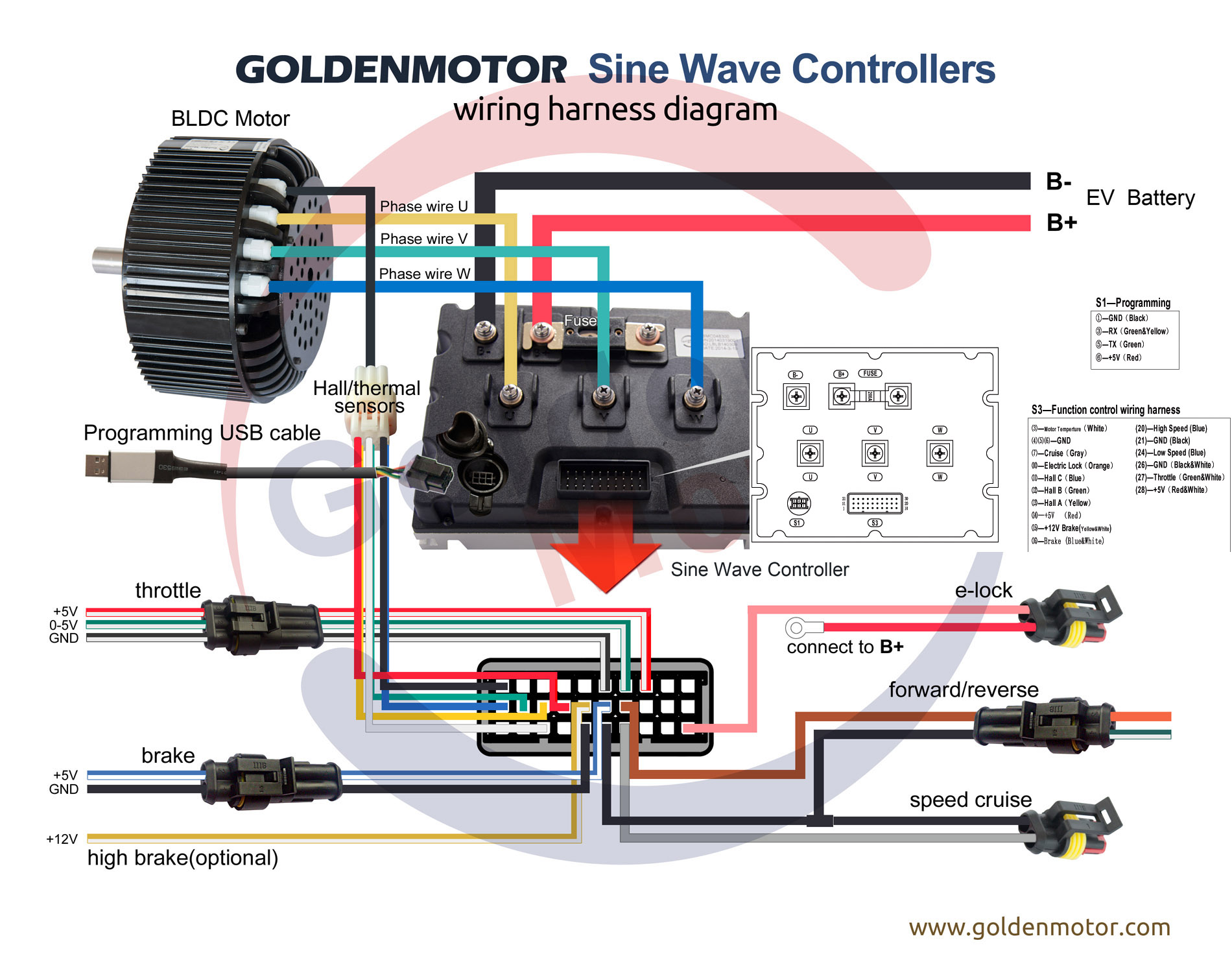
Therefore, I would simply use a separate switch connected to the Brown and Black (Reverse) wires on the controller to select the reverse function (closing the switch contacts should engage Reverse).
Please Note: 48V must not be used to operate the Reverse function.

For the throttle connections you probably need to connect the Black/White wire to Pin 1 (Pot Lo) and the Green/White wire to Pin 8 (0-5V output).
Please Note: the +5V Red/White wire from the VEC300 controller must not be connected to the ET-135 throttle!

Hopefully this wiring diagram below is the same as the ET-135 throttle as the only difference between the two throttles appears to be a return spring fitted to the ET-126:


I suggest that you check the output voltage measured between the (PotLo) and the (0-5V output) connectors using a voltmeter to confirm it is working correctly (and stays within the expected 0-5V range).
This voltage should change progressively from 0V to 5V when the throttle is moved slowly from the OFF position to the FULL THROTTLE position.

If the maximum output voltage exceeds 4.8V then the motor may cut out at maximum throttle position due to the VEC300 controller's throttle protection function.
However, it should be possible to add a 10kOhm variable resistor (or physically limit the full movement of the throttle) to reduce the maximum output voltage to an acceptable value if necessary.

I suggest that you also make a note of the maximum and minimum voltage readings, as they will be very useful if you want to fine tune the throttle range voltages in the controller to closely match the available throttle movement.  ;)

Alan
 
74
General Discussions / Re: VEC300 with 5kW motor
« Last post by Corchard on January 17, 2024, 07:25:16 PM »
Thank you I've been studying those diagrams a lot to try and diagnose the issue.

The wires/connectors  that I will be using are:
  • the Elock (orange)
  • the Throttle (black/white), (green/white) and (red/white)
  • Do I also need to use the forward/reverse (brown) and (black)?

and now for steps:
  • To get the controller to accept signals for the time being I need to connect the elock to the battery and short it to bench test the unit until the switch comes in
  • Then connect the ground (black/white) and 0-5V signal (green/white).  Do I need to do anything with the +5 V red/white or is that connected to the forward signal?  Can it be +48V?
  • Now when I turn the throttle control the motor should spin
  • For Reverse, am I reversing the Brown and black or the red/white and black/white? Again does it matter that the reverse voltage is 48V

Thank you again for your help.
75
General Discussions / Re: New member with dual motor setup
« Last post by Bikemad on January 17, 2024, 12:45:49 PM »
I'm pleased to hear that you've got both motors working, but the 902 mini motors are unable to produce any torque in reverse due to the internal unidirectional clutch.

Without know what voltage motors and battery you are using it is difficult to know what the best settings will be, but I would not set them anywhere near the controller's maximum settings as passing too much current through the mini motors can strip the teeth off the nylon gears and also overheat the windings, which sometimes melts the insulation on the wires resulting in a short circuits:


Drawing just 10 amps at 36 volts (or 15 amps at 24 volts) equates to 360 watts, which should produce an output power of 288 watts at 80% motor efficiency, which is already more than the 250 watt rated power for the mini motors.

However, I suspect that your smaller diameter wheels and dual motors will be less susceptible to overheating as they should be under a lot less load than an identical single motor in a larger diameter wheel.

Alan
 
76
General Discussions / Re: New member with dual motor setup
« Last post by Rlarcier on January 17, 2024, 11:31:24 AM »
Hi Alan

Tx a million for your guidance

I managed to connect to both controllers using the right software and once I had set the same settings ,both engines started to work together.

I'm currently doing 5 full cycles of charge and discharge to break in the new battery. I was told to do 5 full cycles in totals before settings the Amp back from 5 to 30 continuous and from 20 to 50 peak in the controller config
Do you agree with that ?

Once I have done the break in of the battery I will give it a try at your suggestion to use the throttle wiring instead to use one or 2 engines or both

The reverse switch on the Accel switch is also not working although both controllers have the reverse switch set to enable and I tried - immed and unimmed mode without luck - any thoughts, not that a must have but just fun :-)

Need to fix the rear suspension as the rear shock doesn't seem to coop with my weight. Seems to loose air pressure. I will install another one to see if better

For the rest happy I managed to get it working. The pic of the beast :-)
77
General Discussions / Re: VEC300 with 5kW motor
« Last post by Bikemad on January 17, 2024, 12:16:12 AM »
Hi andto the forum.

That throttle should work fine with an output voltage is 0~5V.

The Orange e-lock wire simply requires battery voltage to be applied via a switch to activate the controller, opening the circuit disables the controller.

Reverse is achieved by switching the Reverse wire to ground.

The diagrams below will hopefully help you identify the connections required in order to plan your wiring harness:


Alan
 
78
General Discussions / Re: Eggrider Question
« Last post by Chuy on January 15, 2024, 09:58:49 PM »
I did that first, my measurement is 2045. I’ve changed it up to 2065 and have not noticed a change in odometer readout. It has corrected speed reading. I will try larger increments.
79
General Discussions / VEC300 with 5kW motor
« Last post by Corchard on January 15, 2024, 09:28:35 PM »
Hello Forum,
     I just recently vector 300 w 5km Air cooled and am trying to desk test it before I install it in my sailboat.   I'm trying to determine how (if) I can use a ET-134 throttle controller instead of the rather large heavy one that Golden motors has for sailboats.

the et-134 has 48V input which I can get from batteries (switched and fused) and produces the  0-5V necessary Green-white throttle wire.  So far I haven't been able to get the motor to move.   What else is the controller expecting and on what wire? What signals are required to indicate reverse?   

In terms of shutting down the controller, is the e-lock (Orange wire) just a switch (closed/open circuit)? or is it expecting a signal of some sort?

Unfortunately the vector controllers don't have a proper schematic for the control wires that I have found so that I can plan my wiring harness.

Any help that anyone can provide would be useful.
80
User Guides/Catalog / Re: light and horn
« Last post by Bikemad on January 13, 2024, 10:44:42 AM »
Is the lower arm always horizontal?

Chainstays typically slope downwards slightly towards the bottom bracket:


But here are a couple of exceptions:


The angle between the seat stays and the chainstays can also vary significantly on non-suspension frames.

I've been told there are adapter brackets available for frames without discs.  Any input on that avenue?

You obviously didn't click on the hyperlink in my initial reply to this bolt on adapter kit or you would have seen this adapter bracket:


As previously mentioned, I have not tried any of these kits and I'm not sure how suitable they would be for your particular frame or for use with a 14mm diameter axle.

Alan
 
Pages: 1 ... 6 7 [8] 9 10