Hi Guy,
In your particular case, the maximum current that the switch needs to handle will be determined by the maximum current setting in the motor's controller, as this will be lower than your battery's maximum 50A.
If you have the controller set to the maximum 30A setting, the switch must be able to withstand this amount of current for short periods.
The
15A switch you suggested would be able to supply the required 30A motor power
if both pairs of contacts were wired in parallel, but it wouldn't be very practical to use as it is a momentary switch instead of a latching switch. Basically you would have to continually hold the switch in the ON position to provide power for the controller.

The switch also needs to withstand the very short, but high current burst that occurs when the contacts are first closed and the current quickly flows from the battery to the controller to fill the controller's capacitors up with battery voltage.
This "precharge" process only takes a fraction of a second, but the high current involved will cause a large spark
(arcing) between the switch contacts every time the switch is turned on after the controller has been powered off for at least 30 seconds.
This arcing will cause burning on the metal surface of the switch contacts, which will eventually result in a high resistance and poor current flow between the contacts.
To prolong the life of your switch, I suggest that you connect a simple push button switch
(along with a suitable current limiting resistor) across the contacts of the main On/Off switch to enable the battery power to be turned on without the switch contacts sparking each time.
To power up the controller you would simply press and hold the "precharge" button for a second or two before switching on the main power switch. This allows the capacitors in the controller to be charged up to battery voltage at a much slower rate, which will eliminate the high current burst that causes the arcing
(and possible failure) of the switch contacts.
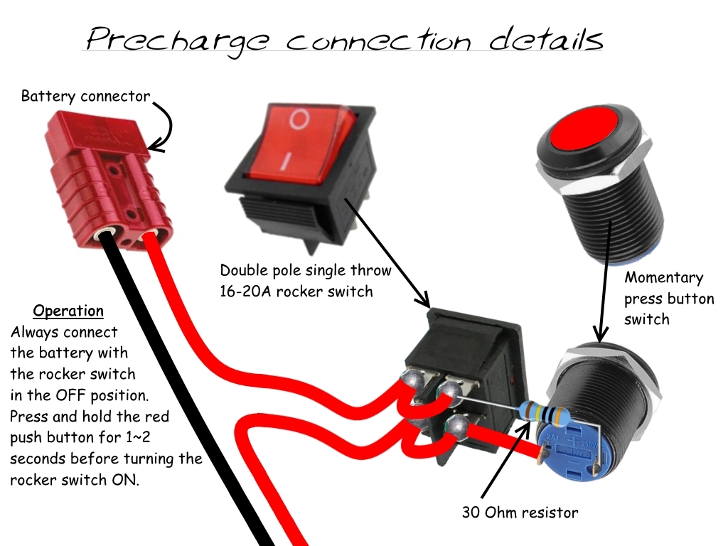
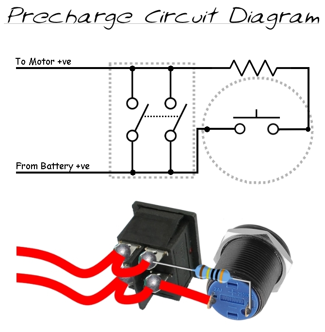
Here is a basic layout showing how the switches and precharge resistor should be wired:


The double pole rocker switch shown in the above diagram has both poles
(pairs of contacts) connected in parallel to enable it to handle twice as much current, as both set of contacts will be equally sharing the total current flow.
This means that a
double pole single throw (DPST) switch with a contact rating of 16A can handle 32A when the current is switched using both sets of contacts.
Check out
this post for more details on the switches.
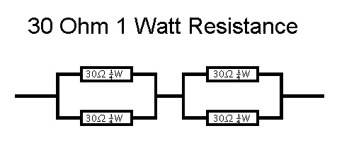
A 1 watt resistor of between 10 and 100 Ohms seems to work nicely with 24V, 36V and 48V batteries, but if you have lights that are powered by the main battery, make sure they are turned off prior to precharging the controller to prevent the resistor from being unnecessarily overloaded while the precharge button is pressed.
If you only have ¼ Watt resistors, you can simply use four resistors wired in a series parallel configuration to produce the same value resistor that can carry four times as much current:

Also, do not try to operate the throttle with the main switch turned off and the precharge button held down, or the high current will burn out the resistor!
I am going to put it on the negative (-) side (post load), so it has less current running through it.
It is common practice to place the switch on the high voltage
(Positive +) connection, as this ensures that you don't have any live wires being supplied with no path to return to ground
(Negative -).
The current flowing through the Negative wire will be identical to the current flowing through the Positive wire, as the current is always the same at any point in a series circuit.
 Alan
Alan