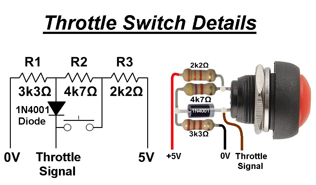
It should be relatively easy to achieve your objective using a momentary "push to make" switch, three resistors and a diode. I will try and post further details when I get chance.
This was what I had in mind:

The colours of your wires connected to the hall sensor may be different to the colours that I have shown in the above diagram, so make a note of what they are before you disconnect any of them from the old hall sensor.
I have sized the resistors to give a switch open throttle signal voltage of ~1V after the 0.6V drop across the diode. This should be high enough not to trigger a throttle fault error, but low enough that the motor will not run
(or cause the throttle safety feature to activate) when you switch the power on.
The switch closed voltage should be ~3.9V, which is high enough to give full power, but not high enough to trigger a high voltage throttle fault
(just in case the controller uses this function).
The resistors could be purchased individually, but I would suggest that you purchase
an assortment of resistors so you have plenty to play with and different values to substitute if the two set voltages need to be altered slightly.
The switch will depend on your existing throttle, and it might be worth seeing if you can disable the latching mechanism on your existing switch to make it into a momentary push switch.
Be careful with the existing wires on the switch as one of the two contacts is connected to the battery main supply voltage and the battery gauge circuit board, these two wires will need to be soldered together and safely insulated.
The other switch connector has a single wire which supplies battery voltage to the LED headlight via the switch. If you have an LED headlight powered by the main battery, you can simply join this wire to the other two wires previously mentioned so the headlamp remains on all the time, or simply insulate it and leave it disconnected if you don't have an LED headlamp already connected.
Alan