Unfortunately no circuit diagram has been released for the wiring harness or the controller board, so when I first received my original MPIII I spent some time identifying what each of the separate connections were and I created this diagram for reference:
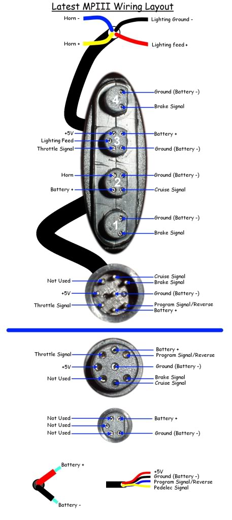
It's probably the nearest thing you will get to a schematic, and without cutting a harness apart I don't know what the colours of the hidden wires are or how the internal joins are achieved. I assume there is a pcb inside the four way multi connector on the front harness, and probably another pcb inside the five cable junction block on the motor harness.
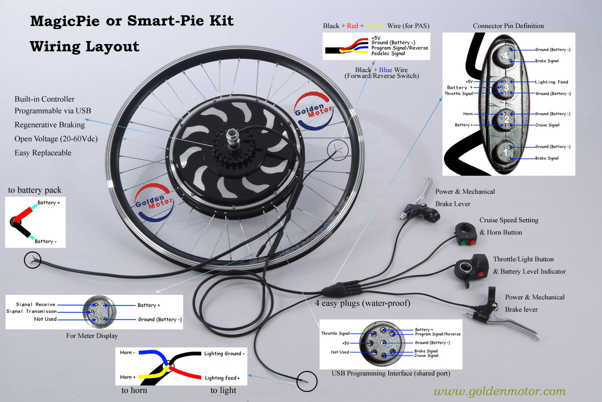
Parts of my diagram were used by GM to create their wiring layout diagram:
The connections to the controller are not shown on the diagram but there are two thicker battery cables
(Red and Black) and six smaller wires:
- Green - Throttle signal
- Blue - Brake signal
- White - +5V supply from controller provides power to Throttle and Pedelec hall sensors (also receives power from USB programming cable)
- Red - Cruise signal
- Black - Reverse & Program Rx
- Yellow - Pedelec signal
There are also two other thin wires in the controller harness that come from the unused five pin connector, but these were simply cut off and not connected inside my early controller, but it's possible that these wires are now being used on more recent controllers:
- Brown - Signal Transmission
- Orange - Signal Receive
I hope this helps.
Alan


