Ok, So today I tried to take apart the throttle. I wanted to see if I was able to directly draw some wiring from there to my cycle analyst.
Would not trie this as the plastic is not just screwed together but also glued. Putting it back together would require glue and taking it apart is taking the risk of unrepairable damage.
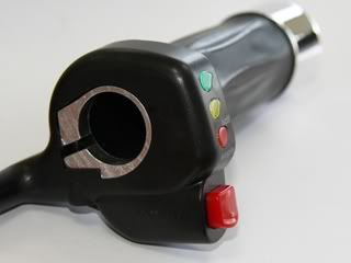
So here is the GM throttle
Opened up it looks like this.
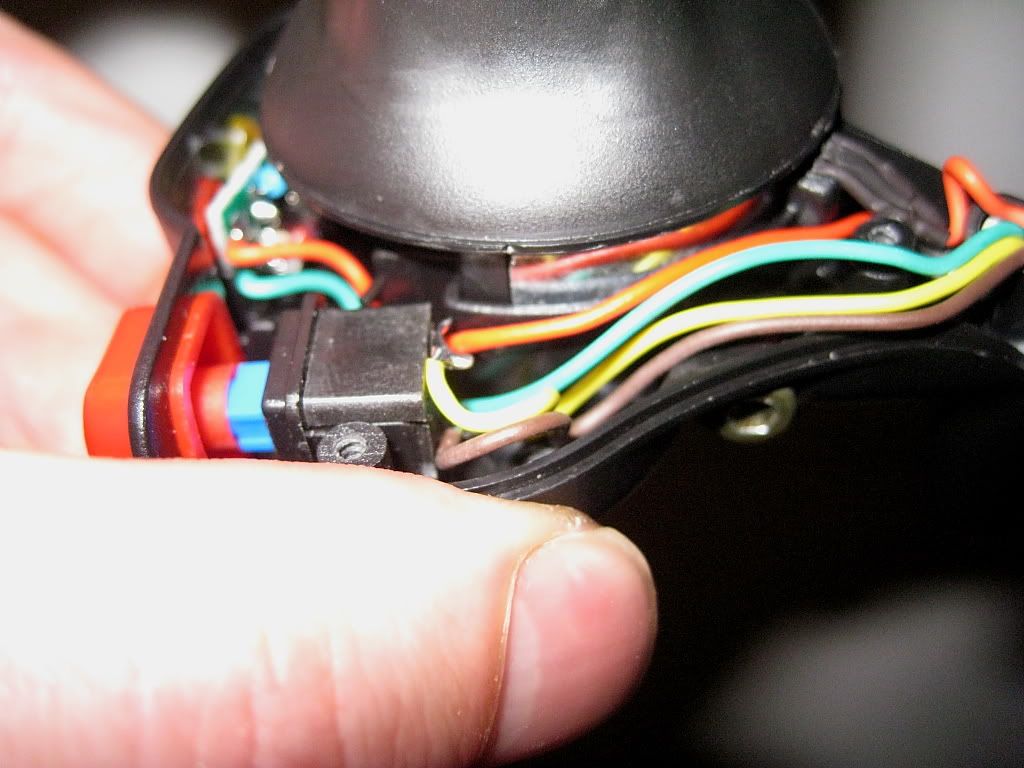
You can see that the brown and yellow wire come together on the red switch.
The green wire goes to the batt lights and must be high voltage....... The red wire going to the batt lights actually is ground. This little red wire is connected to the black coming from the controller.
White red and black however run to a very narrow point.
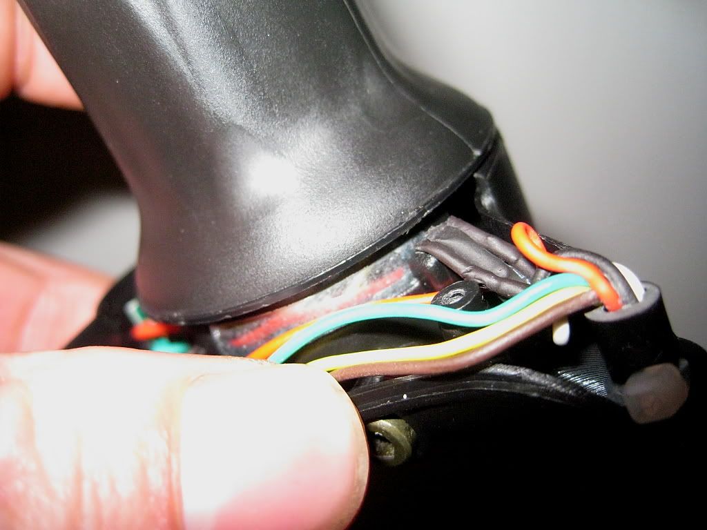
I first thought this was where the wires were leading even deeper into the housing. After some closer examination I thought the Red Black and white came together here in a connector of some sort.
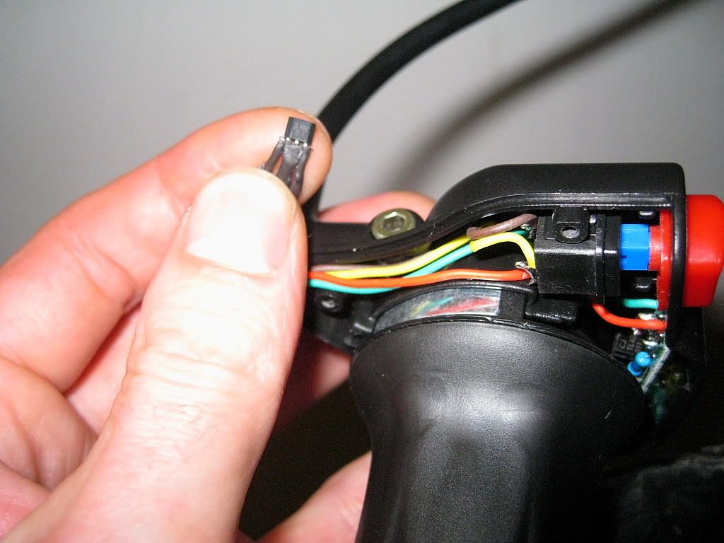
So I did some gentle pulling and wobbling and out it came.....

Examining even closer.....
HUH 
What the....... is this?
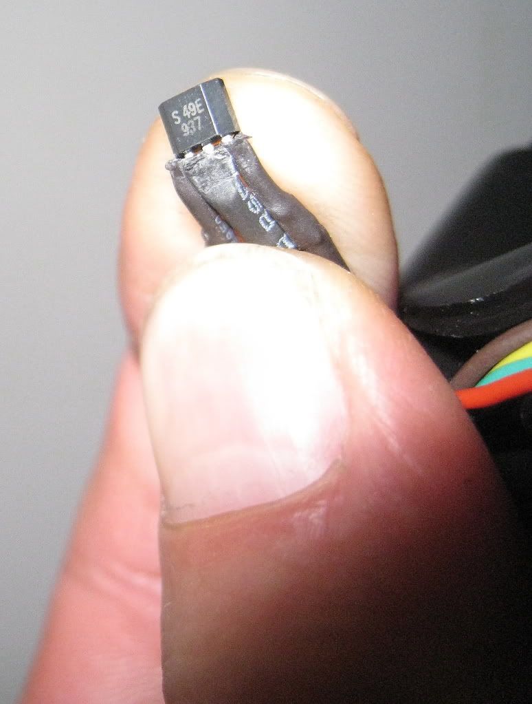
Looks like a sensor of some sort. Could not read the fine print until I took this macro photo.
Have been Googling for this part
S 49E 937
but cant seem to find any information.
I also checked what it could be measuring and I have discovered that the metal ring and moving part of the throttle actually is magnetised. So How would this work?


