Author Topic: Battery Management System - 2x C minus & 2 x B minus ports...  (Read 7423 times)

Offline Bedmountain

  • Confirmed
  • Magic Undergrad
  • ***
  • Posts: 92
Hi guys

I received a BMS today and was surprised to find it had 2 x C- ports and 2 x B- ports.

I was expecting a B-, a C- and a P-

I understand how to wire that up :)

Anyone know how this should be wired?

Many thanks in advance...

Ben

Offline Bikemad

  • Global Moderator
  • Professor
  • PhD. Magic
  • ******
  • Posts: 5,497
Re: Battery Management System - 2x C minus & 2 x B minus ports...
« Reply #1 on: March 16, 2017, 10:25:56 AM »
Hi Ben,

If you can post a picture showing all of the connections on the BMS, it might be possible to work out how it is supposed to be wired.

I'm guessing it uses the C- port as a power output port too, in which case it would then be charged via the output wires (or separate charger wires connected in parallel with the output wires.)

Alan
 

Offline Bedmountain

  • Confirmed
  • Magic Undergrad
  • ***
  • Posts: 92
Re: Battery Management System - 2x C minus & 2 x B minus ports...
« Reply #2 on: March 16, 2017, 06:27:35 PM »
Thanks Alan

The sense wires end (makes sense...):


The 2 x B- connections:


The 2 x C- connections:


Top down:


The product listing:
https://www.aliexpress.com/item/Brand-14s-60A-51-8v-BMS-polymer-lithium-battery-14-cell-battery-protection-bms-board-bms/32722347963.html?spm=2114.13010608.0.0.UgkHvH


Is there any why I can check that it's rated for 51.8v / 60A - for some reason I don't have a lot of trust in Chinese suppliers... :)


Offline Bikemad

  • Global Moderator
  • Professor
  • PhD. Magic
  • ******
  • Posts: 5,497
Re: Battery Management System - 2x C minus & 2 x B minus ports...
« Reply #3 on: March 16, 2017, 10:52:56 PM »
Hi Ben,

I would wire it similar to this diagram:


Your two B- connections (and the two C- connections) appear to be directly linked together along the circuit board therefore it shouldn't make any difference as to which B- or C- connection you use.
You could use a pair of wires in parallel for each pair of connections (or daisychain one B- to the other B- and one C- to the other C-) for better current distribution across the connections as per this diagram:


Alan
 
« Last Edit: May 07, 2020, 01:16:09 PM by Bikemad »

Offline Bedmountain

  • Confirmed
  • Magic Undergrad
  • ***
  • Posts: 92
Re: Battery Management System - 2x C minus & 2 x B minus ports...
« Reply #4 on: March 17, 2017, 08:58:01 AM »
Brilliant - thank you Alan.

So for the C- connections can I take one wire from one of the C- connections to the charger and one wire from the other C- connection to the discharge? And connect a wire from one C- connection to the other C- connection to improve current distribution (or is that unnecessary?). Sorry - doesn't matter how well you explain it I still struggle  ???).

2 last questions (maybe) - the 2 wires already attached with a little rectangular thing on the end. That's a temp sensor right? Does it matter where that is placed? Should I tape it to the outside of the BMS or would it be better sitting between the PCB and the metal cover?
Also - I see a lot of BMS instructions stating that the sense wires must be connected in a certain order. Is it not possible to connect all the wires to the battery and then just connect the 15 pin plug into the BMS?

« Last Edit: March 17, 2017, 01:51:11 PM by Bedmountain »

Offline Bikemad

  • Global Moderator
  • Professor
  • PhD. Magic
  • ******
  • Posts: 5,497
Re: Battery Management System - 2x C minus & 2 x B minus ports...
« Reply #5 on: March 17, 2017, 02:33:26 PM »
Hi Ben,

If you are not intending to draw the maximum 60A current (i.e. supplying dual Pies from the single pack or using a high current external controller etc.) then a single connection on one of the C- connections for the main discharge cable should be fine.

For maximum current draw, I would recommend using a pair of wires soldered to the main discharge negative cable and the charging negative cable as shown in this modified diagram:


Alternatively, you can make up a simple external adapter to allow your charger output to plug directly into the main battery discharge connector, as this would only require two leads coming out of the battery instead of four.

The temperature sensor is usually located within the battery cells to monitor the temperature of the cells - not the BMS.
If it was intended to monitor the BMS temperature the thermistor would be mounted directly to the BMS PCB instead of on the ends of the wires.  ;)

Alan
 
« Last Edit: November 23, 2020, 11:02:32 AM by Bikemad »

Offline Bedmountain

  • Confirmed
  • Magic Undergrad
  • ***
  • Posts: 92
Re: Battery Management System - 2x C minus & 2 x B minus ports...
« Reply #6 on: March 17, 2017, 02:47:13 PM »
Thanks Alan - I understand the wiring now :D...

For the temp sensor I'm still a little confused. You say it should be located within the battery cells? So I need to locate it somewhere between the cells?

Also on the connection order. Can I connect all the sense wires to the plug then plug it in or does it have to be plugged in and connected in order?

Thanks for your patience :)...

Offline Bikemad

  • Global Moderator
  • Professor
  • PhD. Magic
  • ******
  • Posts: 5,497
Re: Battery Management System - 2x C minus & 2 x B minus ports...
« Reply #7 on: March 17, 2017, 07:20:52 PM »
The ideal position for the temperature sensor (thermistor) is between the cells in the centre of the pack, as this is typically the part that will get the hottest:
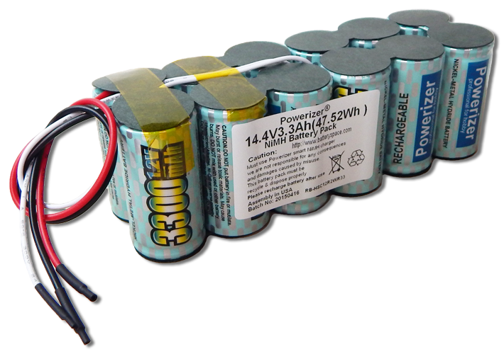


(If you don't have room between the cells, you can simply attach it between two of the outer cells using hot melt glue)

You can (and really should) connect all the wires from the balance lead connector to their respective cell connections before plugging in the connector, and you must also ensure that they have been connected in the correct sequence from cell 1 negative to cell 14 positive.

It is a good idea to use a voltmeter to ensure the connector pins increase in voltage by the actual cell voltage from the battery negative end of the connecter (Usually pin 1):

Pin 1-> 2 = ~4V
Pin 1-> 3 = ~8V
Pin 1-> 4 = ~12V
Pin 1-> 5 = ~16V
Pin 1-> 6 = ~20V
Pin 1-> 7 = ~24V
Pin 1-> 8 = ~28V
Pin 1-> 9 = ~32V
Pin 1->10 = ~36V
Pin 1->11 = ~40V
Pin 1->12 = ~44V
Pin 1->13 = ~48V
Pin 1->14 = ~52V
Pin 1->15 = ~56V

The above readings are what you would expect to see with an average cell voltage of ~4V per cell.
It is important to make sure all of the cells in the pack are at approximately the same resting voltage before assembling the pack, or the BMS may struggle to balance the completed pack.

They do not necessarily need to be at the ~4V shown in the above example, what really matters is that they should all be at a similar voltage (similar state of charge).
(The resting voltage of all the cells could be 3.7V, 3.75, 3.8V, 3.85V etc. or even as high as 4.2V, just as long as they are all at approximately the same voltage)

If the voltage readings are not in a regular ascending order, DO NOT PLUG THE BALANCE LEAD CONNECTOR INTO THE BMS SOCKET until the incorrect wiring connections have been rectified, or you are likely to damage the BMS and/or the balance lead wires.  :o

I hope this all makes sense.


Alan
 
« Last Edit: July 04, 2017, 09:13:05 PM by Bikemad »

Offline Bedmountain

  • Confirmed
  • Magic Undergrad
  • ***
  • Posts: 92
Re: Battery Management System - 2x C minus & 2 x B minus ports...
« Reply #8 on: March 18, 2017, 09:24:23 AM »
Brilliant - makes perfect sense - thanks Alan

Cells should be arriving soon.

Tales of disaster to follow...  :o

Offline Bedmountain

  • Confirmed
  • Magic Undergrad
  • ***
  • Posts: 92
Re: Battery Management System - 2x C minus & 2 x B minus ports...
« Reply #9 on: March 20, 2017, 12:28:36 PM »
Just one more thing :)...

I was planing to use 10awg wire for the discharge and 14awg for the charge.

Does that sound big enough?

I'd like to understand how to calculate the required thicknesses but I'm struggling to find anything that makes sense to me.

Offline Hastings

  • Confirmed
  • Magic Undergrad
  • ***
  • Posts: 61
Re: Battery Management System - 2x C minus & 2 x B minus ports...
« Reply #10 on: March 20, 2017, 06:45:37 PM »
Sounds right . I use 6 mm2 to run the bike from a 48v / 15Ah  battery and 2,5 mm2 for charge. I have never overheated the cables but the connections on the BMS as well as the fuse connectors. Today I use Maxi fuses because the holders have sufficient metal surfaces and contact surfaces not to become overly hot

Offline Bikemad

  • Global Moderator
  • Professor
  • PhD. Magic
  • ******
  • Posts: 5,497
Re: Battery Management System - 2x C minus & 2 x B minus ports...
« Reply #11 on: March 21, 2017, 10:23:13 PM »
I'd like to understand how to calculate the required thicknesses but I'm struggling to find anything that makes sense to me.

There is a shortcut to a post about wire gauges in the Useful Links section which has a useful wire gauge table attached showing current carrying capabilities of different sized wires.

My Turnigy 4S 20C 5Ah packs have 12 swg cables with 4mm Bullet connectors, and these packs are rated for 100A continuous discharge and 150A peak.
My Zippy 8S 25C 5.8Ah pack has 10 swg cables with 5.5mm Bullet connectors, and these packs are rated for 145A continuous discharge and 203A peak.

According to this table on powerstream.com 12 swg is good for 41A and 10 swg is good for 55A, but I have passed over 97A through 12 swg wires and the wires were fine:


Alan
 
« Last Edit: July 04, 2017, 09:12:42 PM by Bikemad »

Offline Bedmountain

  • Confirmed
  • Magic Undergrad
  • ***
  • Posts: 92
Re: Battery Management System - 2x C minus & 2 x B minus ports...
« Reply #12 on: March 22, 2017, 08:58:02 AM »
Nice one - thanks guys... Great info.

Offline Bedmountain

  • Confirmed
  • Magic Undergrad
  • ***
  • Posts: 92
Re: Battery Management System - 2x C minus & 2 x B minus ports...
« Reply #13 on: March 23, 2017, 09:23:56 PM »
I've been stressing about the wires from the battery discharge being thick enough but looking at my existing connections between the battery connector and the controller I will be pushing the current through a switch via some pretty thin wires:


and the wires back to the controller after the shunt are pretty thin too (pretty sure that was the cable that came out of the box with the MP5:


Are these wires woefully thin? Surely it doesn't make any difference having 8 or 10awg discharge wires from the battery if the current has to squeeze through these later on? Do I need to re-wire the switch and the wiring between the shunt and the controller with something thicker? The shunt is sealed so I can't upgrade that so surely any wire thicker than the shunt wiring is a waste of time anyway?

Offline Bikemad

  • Global Moderator
  • Professor
  • PhD. Magic
  • ******
  • Posts: 5,497
Re: Battery Management System - 2x C minus & 2 x B minus ports...
« Reply #14 on: March 29, 2017, 05:12:53 PM »
Hi Ben,

Thinner wires produce more voltage drop along their length which can produce a very noticeable voltage drop at the motor if the wires are long as well as thin.

If your wires are getting noticeably warm to the touch when the motor is under heavy load then it might be better to use thicker wires.
If the wires are not getting warm, and the motor still performs nicely, then there is no need to worry.

Thicker wires will have less voltage drop along their length, so the voltage available at the motor will be higher, therefore the motor will produce slightly more power for the same current draw.

Ideally the wires should be as thick and as short as possible for maximum power and efficiency, but in practice, this is not always feasible.

Ideally, the resistance in the battery circuit should be as low as possible, and this includes the internal resistance of the battery itself.
A battery with a high internal resistance will produce less motor power than an identical battery with low resistance.
The higher voltage drop caused by the high resistance within the battery cells will also generate more heat within the battery when it is under load compared to the identical battery with low resistance.  ;)

Alan
 
I apologise for the delayed response, but we had to have our ten year old dog (Heidi) put to sleep on 23rd March as she would no longer eat and was wasting away because of liver cancer.
This photo was taken during an enjoyable walk on the beach just two hours before going to sleep for the very last time:
« Last Edit: July 02, 2017, 07:39:37 PM by Bikemad »